

There is no universal solar panel clamp torque, even when two assemblies use the same nominal bolt size. The correct value is the torque specified for the exact combination of PV module frame, clamp, bolt, nut or channel insert, and mounting rail. It must also fall within the limits in both the module installation manual and the mounting-system documentation.
If those documents disagree, do not average the numbers or choose the lower value by habit. Pause that assembly and obtain a written resolution from the responsible suppliers or project engineer. Torque is only an indirect way to create bolt preload; a familiar value copied from another system can leave one module loose and damage another.

What Determines the Correct Solar Panel Clamp Torque?
Start with the module model and its permitted clamping zones, then match the approved solar panel clamps, fasteners, and rail interface. The controlling torque should come from documentation that covers this complete assembly—not from bolt diameter alone.
This distinction matters because the module manufacturer sets limits for the aluminum frame, while the mounting-system supplier validates how the clamp and fastener develop holding force. A torque that is acceptable for the bolt may still overload a thin module frame, deform a clamp, or damage a rail channel. Conversely, a value chosen only to protect the frame may not produce enough preload to prevent movement under cyclic wind loads.
Treat the approved torque as a component-specific value or range. Record its source and document revision in the installation method statement before work begins.
How Do Fastener and Clamp Variables Change Torque?
Torque creates rotation; preload creates clamping force. Friction consumes much of the applied torque, so apparently small changes in the assembly can produce a large change in preload.
Fastener Geometry and Friction
An often-used engineering estimate is:
T = K × F × d
Here, T is tightening torque in N·m, K is a dimensionless nut factor representing friction, F is estimated bolt preload in newtons, and d is nominal bolt diameter in metres. The relationship is an approximation, not a substitute for tested assembly data.
For an illustrative M8 bolt tightened to 16 N·m, using K = 0.20 gives an estimated preload of 10,000 N. If lubrication or a coating reduces K to 0.12, the same torque produces an estimate of about 16,700 N—a 67% increase. That difference can be enough to shift the risk from insufficient holding force to damaged threads or components.
Bolt grade, thread pitch, coating, lubrication, washer arrangement, engagement length, and the bolts and nuts selected for the racking assembly all affect the result. “M8” identifies a size, not a complete torque specification.
Clamp and Module Interface
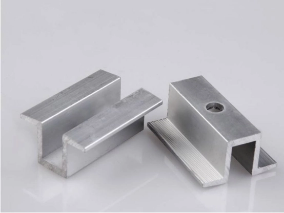
Clamp length, bearing area, serrations, material stiffness, and bolt position determine how preload reaches the module frame. Frame height, wall thickness, clamping zone, rail shape, and channel-nut engagement also matter. Mid clamps and end clamps may look similar but can have different load paths. Replacing one item with a visually compatible alternative invalidates the original torque assumption unless the complete combination is reapproved.
What Happens When Clamp Torque Is Too Low or Too High?
Both errors can remain hidden after installation. A clamp may appear seated while its preload is outside the intended range.
Effects of under-Tightening
Insufficient preload can allow small relative movements between the clamp, frame, and rail. Repeated wind cycles may then cause slip, fretting marks, noise, or gradual loosening. Loads can become unevenly distributed across neighboring clamps, increasing demand on individual connection points. Where an approved bonding function depends on listed hardware, inadequate seating may also compromise that function; never assume every clamp provides electrical bonding.
Effects of over-Tightening
Excessive preload can indent or distort the module frame, yield the clamp, strip threads, or damage the rail nut and channel. The joint may still feel tight even after a component has started to deform. Over-tightening can also make future removal unpredictable and may conflict with module or mounting-system warranty conditions. An impact driver increases this risk because its peak output may exceed the setpoint before the operator reacts.
How Should Solar Clamp Torque Be Specified and Verified?
The goal is one resolved requirement for each approved assembly and a field process capable of reproducing it.
Resolve the Specification Before Installation
Create an assembly record that identifies the module, clamp, bolt, washer, nut or insert, and rail by model and revision. Compare the module manual with the mounting documentation. Confirm the required torque value or range, whether threads must be dry or treated, whether hardware is reusable, and which tool method is permitted.
If the documents specify incompatible values, the assembly is not ready for installation. Obtain a written project-specific decision rather than selecting an average. Also separate clamp-bolt torque from structural-joint torque: purlin, brace, or foundation connections may use different fastener grades and design assumptions.
Control and Record the Installation Process
Use powered tools for initial rundown only when the approved method allows it. Complete final tightening with a calibrated torque tool whose working range suits the setpoint. Keep the socket square to the bolt, follow the specified tightening sequence, and avoid repeated clicking, which can add preload.
Record the tool ID, calibration status, setpoint, hardware lot or work area, date, and installer. A supervisor can audit a defined sample with the approved verification method. Witness marks help identify completed joints, but they show movement—not actual torque. Replace damaged, cross-threaded, contaminated, or unapproved hardware instead of forcing it to the nominal value.
Which Project Data Must Be Matched Before Tightening?
The torque decision should be traceable to the exact parts and conditions in the field.
| Data Group | Information to Match | Why It Matters |
| PV module | Model, frame height, clamping zone, manual revision | Defines permitted contact areas and frame limits |
| Clamp | Mid or end type, geometry, material, drawing revision | Controls load transfer and bearing area |
| Fastener | Diameter, pitch, grade, coating, washer, thread engagement | Changes strength and torque-to-preload behavior |
| Rail interface | Rail model, channel nut or insert, engagement | Determines thread support and joint stiffness |
| Surface condition | Dry, lubricated, coated, contaminated, or threadlocked | Changes friction and resulting preload |
| Site method | Tool type, calibration, access, reuse rule, environment | Affects repeatability and inspection planning |
FAQ
These questions address common site decisions that should be resolved before tightening begins.
Can One Torque Value Be Used for Every M8 Solar Clamp?
No. M8 describes nominal thread diameter, but not bolt grade, pitch, finish, lubrication, engagement, clamp geometry, rail nut, or module-frame limit. Use the documented value for the exact approved assembly.
Should Threadlocker Be Added to Solar Clamp Bolts?
Only when the approved assembly documentation permits it. Liquid or pre-applied threadlocker can change friction, which changes preload at the same torque. Adding it without validation may therefore make an otherwise correct setpoint unsuitable.
Is a Click-Type Torque Wrench Sufficient for Installation?
It can be, provided its range is appropriate, calibration is current, the socket fits correctly, and operators use a consistent technique. The project should also define how completed work is sampled or audited.
Should Solar Panel Clamps Be Re-Torqued After Installation?
Follow the approved maintenance procedure. Arbitrary re-torque can rotate settled hardware or increase preload. Begin with periodic inspection of PV support brackets, document movement or damage, and tighten only as the responsible documentation directs.
What If the Module and Mounting Instructions Disagree?
Stop work on that assembly and request a written resolution from the module supplier, mounting-system supplier, or responsible engineer. Do not average conflicting values, and do not assume the lower value satisfies both systems.
What Should You Send for a Clamp Compatibility Review?
Before purchasing or installing a clamp combination, send us the module and mounting documents together with the module model, frame height, clamping zone, clamp drawing, bolt specification, rail or channel details, surface condition, site environment, and intended tightening method. That information allows the assembly—and its torque requirement—to be reviewed as one system.








 English
  Japanese
  Korean
  Spanish
  Arabic
  Russian
  French
  Thai
Thai