

EV charging and battery equipment can change a solar carport’s structural design even when the PV roof area stays the same. Treat each charger, cabinet, cable tray, and protection post as a defined load with a location and support path. The combined effects of equipment weight, eccentricity, cable reactions, vehicle impact design, wind, and snow determine whether the selected members and foundations remain suitable.
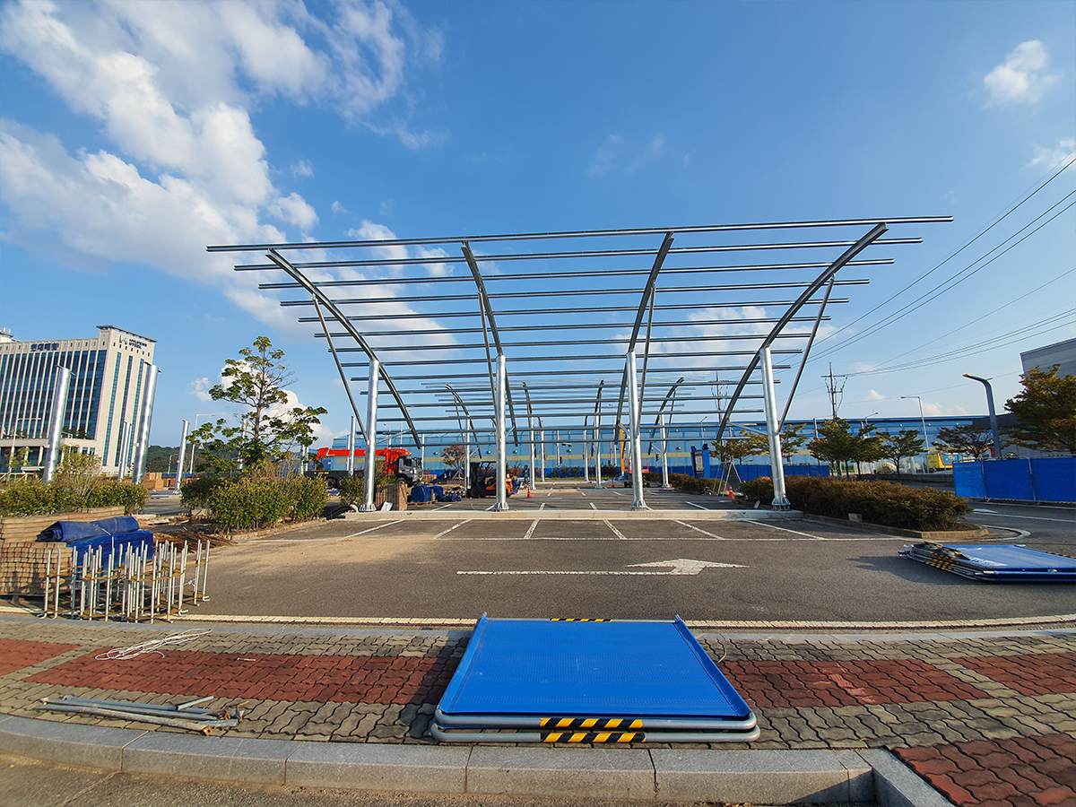
The useful design question is not simply how many kilograms the equipment adds. It is where those forces enter the frame, how they combine with the governing environmental cases, and whether the connections can transfer them into columns and foundations. A solar carport structure such as a steel carport solution therefore needs equipment interfaces coordinated before member sizes and connection details are finalized.
What Load Cases Should Be Included for EV Charging Equipment?
Start with an equipment schedule and vendor drawings. For every component, record its operating weight, dimensions, center of gravity, mounting points, and the structure that supports it. A charger attached to a column creates a different local effect from a cabinet on a ground plinth, even if both have the same mass.
| Load source | Structural effect to consider |
|---|---|
| Charger, inverter, or battery enclosure | Permanent load and local connection forces |
| Offset bracket or wall arm | Eccentric moment and possible torsion |
| Cable tray and cable bundle | Distributed load plus concentrated hanger reactions |
| Bollard or impact barrier | Separate vehicle-impact case and foundation demand |
| Maintenance access | Applicable imposed load and clearance requirements |
| Wind, snow, and seismic actions | Combinations under the project’s governing code |
Do not combine every maximum value automatically. The structural engineer should establish the applicable load combinations, factors, and accidental cases under the project jurisdiction and design standard. Keep equipment loads distinct from PV module and rail loads so that a later charger change can be traced through the model.
How Do Added Loads Change Steel Member Selection?
Local equipment reactions can govern a member even when the overall carport roof load changes only slightly. A cabinet mounted halfway up a column, for example, introduces a concentrated horizontal or vertical reaction at a specific height. That force may increase column bending, connection demand, or local plate stresses. A cable support attached between frame nodes can also introduce a reaction the original analysis did not include.
For an illustrative sizing check, assume a 180 kg charger cabinet and a 60 kg cable tray are supported by one beam line. Their combined gravity force is approximately:
W = (180 + 60) kg × 9.81 m/s² = 2.35 kN
This value is only the unfactored gravity force. It does not include load factors, tray span reactions, dynamic or impact actions, wind on the equipment, connection eccentricity, or load sharing with adjacent supports. The equipment schedule and support arrangement determine how the 2.35 kN is distributed.
For steel member selection, check strength and serviceability at the actual attachment points. Depending on the frame, the critical response may be column bending, beam deflection, torsion, local web or flange behavior, brace force, or connection slip. The 탄소 강철 태양 전지판 구조 should be evaluated as a connected frame, not as isolated catalogue sections. Member capacity depends on span, restraint, steel grade, connection stiffness, corrosion allowance where applicable, and governing design code.
How Does Equipment Position Affect Eccentricity?
An offset between a load and the member’s reference axis creates a moment: M = W × e, where M is moment in kN·m, W is the force in kN, and e is the perpendicular offset in metres. If the 2.35 kN illustrative load acts 0.30 m from a column face, the additional moment is 0.705 kN·m before design factors. A larger stand-off or one-sided bracket can also introduce torsion. Use the vendor mounting coordinates, not the equipment enclosure center alone.
What Foundation Checks Follow from Charger and Battery Loads?
Equipment changes at the top of a frame can flow down to column bases and anchors. A heavier cabinet may increase compression, while an offset or wind-exposed unit may increase bending and anchor tension. If a charger plinth, battery pad, and carport footing share a slab or nearby ground, their loads and clearances must be coordinated with civil design.
Foundation review should use the reactions from the structural model, including uplift, overturning, shear, and compression combinations. The soil report, groundwater and drainage conditions, pavement build-up, buried utilities, and equipment maintenance access can all affect the foundation interface. A separate plinth may simplify the load path, but it does not remove the need to check interaction, vehicle clearance, cable routing, and impact protection.
Do not size a footing from equipment mass alone. The governing case may be wind on the carport, overturning from an eccentric support, or a code-defined impact action at a barrier. Confirm which discipline owns each load and where that load enters the model before the foundation drawings are released.
What Equipment Data Should Be Sent for Structural Review?
The review needs two separate data groups: the equipment and site conditions that define the loads, and the interface details that determine how those loads enter the frame.
Which Equipment and Site Data Are Needed?
Provide the equipment schedule, vendor general-arrangement drawings, operating and shipping weights where relevant, center of gravity, support reactions, mounting-hole coordinates, cable tray routes, and any specified impact or access conditions. Add the site design criteria, applicable code and load combinations, geotechnical report, corrosion exposure, pavement information, and required vehicle clearances.
What Interface Data Is Needed for Custom Parts?
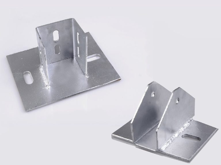
For interfaces that use a custom bracket or plate, include the mating member geometry, hole pattern, material and coating requirements, and installation access. These details help the team assess whether custom metal parts can form a practical connection within the approved design. Freeze equipment positions and support reactions before releasing steel fabrication; if vendor data changes, update the structural model and connection review.
자주 묻는 질문
Does an EV Charger Always Need a Separate Support Frame?
No. A charger may be supported by a carport column or a separate post if the equipment loads, access, clearance, connection design, and load path have been checked. The support choice depends on the actual frame and equipment arrangement.
Should Battery Cabinets Be Counted As Roof Dead Load?
Only when the roof frame is the approved support. A cabinet on a ground plinth or column-mounted platform follows a different reaction path and should not be spread across roof members by assumption.
How Should Cable Trays Be Included in the Structural Model?
Use the tray and cable weight, support spacing, span, attachment points, and concentrated hanger reactions. Include thermal movement and routing constraints where these affect the supports.
Do Charger Foundations Change the Solar Carport Column Design?
They can. Shared slabs, separate plinths, anchors, barriers, and cable trenches affect reactions and clearances near the column line. Coordinate the civil and structural interfaces before finalizing foundations.
What If Equipment Data Is Not Final?
Set a documented design envelope for mass, center of gravity, mounting position, and cable support reactions. Update the calculations when vendor drawings and final support details are available.
Closing: Align the Carport Frame with the Equipment Before Release
Before releasing steel or foundations, reconcile the equipment schedule with the structural model and confirm where each reaction enters the frame. To coordinate an interface review, send the equipment schedule and site loads with mounting drawings, design criteria, foundation information, and equipment coordinates.






 Korean
  English
  Japanese
  Spanish
  Arabic
  Russian
  French
  Thai
Thai