

Imagine setting a rail gap at eight in the morning, while the steel is still cool. Return after several hours of sun and the opening could be smaller. There are two lengths to look at here: the rail to your left and the rail to your right. Where is each one anchored?
To work out solar mounting rail thermal expansion, we use ΔL = α × L × ΔT for free growth. The next step takes more thought: working out which end receives that growth. A 24 m steel run warming by 50°C grows about 14.4 mm with the coefficient used below. We would want to see its fixed point marked before putting a gap dimension on the drawing.
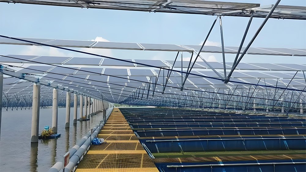
How Much Can a Solar Mounting Rail Move?
A gap copied from a short table can look quite reasonable on a longer row. The hardware matches, after all. But extra steel between the fixed point and the joint means extra travel at that joint.
In the formula, L is that freely moving length in metres. ΔT is the rail’s temperature change in °C. Multiply them by α, the expansion coefficient, to get ΔL, the change in metres.
For this steel calculation, we’ll use α = 12 × 10⁻⁶/°C. It falls within the 10.8–12.5 range, in millionths per degree, in the linear expansion coefficient table. Aluminum’s listed value is 23 in the same units.
One detail is easy to miss while laying out a carbon-steel solar structure: the temperature on a phone’s weather app is an air reading. The steel sitting in sunlight may be hotter. Use the installation metal temperature as your starting point and compare it with the design’s hot and cold metal conditions.
What Does a 24-Metre Rail Example Show?
Here is a calculation example, with the rail at 20°C when installed. Its hot design temperature is 70°C. Subtract the two and you have a 50°C rise over a 24 m run.
ΔL = 12 × 10⁻⁶ × 24 m × 50°C = 0.0144 m = 14.4 mm
Nearly a centimetre and a half. Hold one end still and let the rest slide freely: the far end takes that whole movement.
Now cool the steel to -10°C. It is 30°C below the installation temperature, so the same multiplication gives 8.64 mm of contraction. From the coldest to the hottest condition, the difference in length is 23.04 mm.
|
Metal Condition |
Temperature Change From 20°C Install |
Free Length Change |
|---|---|---|
|
Cold rail at -10°C |
-30°C |
-8.64 mm |
|
Hot rail at 70°C |
+50°C |
+14.40 mm |
|
Full cold-to-hot range |
80°C |
23.04 mm |
Those values assume free steel expansion. Before applying them to a C-steel channel run, check how it is restrained. A continuous row of tightly clamped supports will not behave like the freely sliding rail in this example.
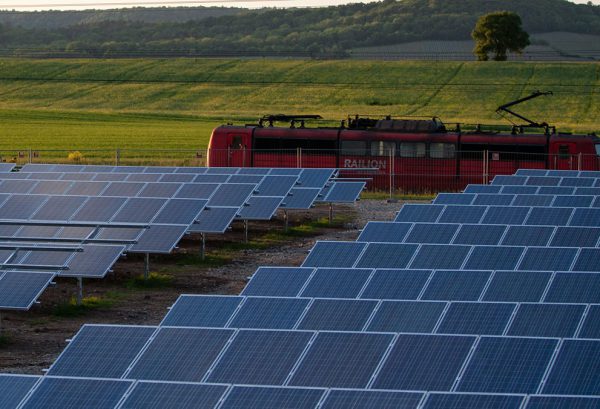
Where Should Fixed Points Go?
On the drawing, find the point that holds the rail’s reference position. Trace the length from there to each free end. That is a more useful exercise than starting with the overall row length.
Move the fixed point in our example to the centre. You now have 12 m growing in each direction. With the other supports allowing axial sliding, the hot movement at each end drops to 7.2 mm. The steel has not become less expansive; you’ve shared the growth between two ends.
We would consider a central fixed point where sharing the end travel helps the layout. It still needs a suitable support and load path. And check what is underneath: a moving support line changes the relative travel at the joint. The convenient assumption of a stationary base deserves a look at the structural drawing.
How Should a Rail Gap Be Set?
Put two arrows beside the joint, one for each rail end. They make the gap calculation and the hardware check easier to separate.
Count the Movement from Both Sides
If two 12 m lengths each grow 7.2 mm toward the same opening, they close it by 14.4 mm together. Leaving 7.2 mm because that is “one rail’s movement” misses half the demand.
There is another number to write next to those arrows: the temperature when you set the gap. At a 55°C installation temperature, our example has 15°C of warming left before reaching 70°C. Assemble it at 10°C and that remaining rise becomes 60°C. We’d expect different settings on those two days. Allow for fabrication tolerances as well, and check that enough of the connector stays engaged when cold steel pulls the ends apart.
Keep the Joint Free to Do Its Job
A purlin connection joins members; a sliding detail must also provide a deliberate movement path. Being able to slide along the rail does not remove the need to resist wind uplift or sideways force. We’d want both behaviors resolved on the drawing before assembly. Simply backing off a structural bolt leaves you with a loose connection.
Watch the modules above the break. A frame or clamp spanning independently moving rails can tie them back together. Review the rail clamp fit there, along with bonding parts and cable crossings.
How Should You Review a Rail Layout on Site?
Walk the drawing with the installer and mark six things:
The measured rail length between movement breaks.
The steel temperature at installation, not only the weather-station reading.
Every fixed point and the direction each free end is expected to move.
The splice gap, overlap, and connection type shown in the detail.
Any module or clamp that crosses the break.
Cables and bonded metal parts that need a designed allowance at the same location.
If the drawing has no fixed-point marks, stop there. A gap without a movement map is just a dimension. Set the drawing beside the delivered rail and bolt-and-nut hardware. A slotted hole may look promising. What keeps the tightened assembly from locking it? That question needs an answer in the connection detail.
What Should You Send for a Rail Layout Review?
Send a marked-up plan for a rail layout discussion with us. Include the rail section and its uninterrupted lengths. Mark support spacing and fixed points, then attach the splice detail and design metal-temperature range. Add the expected installation temperature if you have it.
That gives us something concrete to work through: how far each end travels and whether the surrounding parts leave it room.
FAQについて
Is Steel Movement Smaller Than Aluminum Movement?
Yes. The typical coefficients above put aluminum at roughly twice the movement of the selected steel value for the same length and temperature change. That does not make steel joints immune to movement. Long steel rails still accumulate millimeters quickly.
Should Air Temperature Set the Rail Gap?
Use metal temperature. Shaded air and sunlit steel are different starting points. For the gap setting, you need the steel temperature during assembly plus the hot and cold metal conditions on the design drawing.
Can Tight Bolts Eliminate Thermal Movement?
A tightly bolted joint may hold the rail in place. The steel still tries to grow, though, and that restraint puts force into the connection and its supports. Look for a specified sliding detail where movement is intended; tightening every joint alike changes the movement layout.
Do Modules Need a Break at the Rail Break?
Check the module layout and clamp detail. A module frame or clamp spanning two rail sections can bridge the structural break and transfer movement into parts that were expected to move independently.





 Japanese
 English
 Korean
 Spanish
 Arabic
 Russian
 French
 Thai