

A solar carport layout for a fleet depot should start with vehicle movement and charging windows, then fit the canopy, columns, PV capacity, and electrical equipment around those operating constraints. A layout that works for ordinary parking can fail when buses, vans, or trucks must arrive, charge, queue, and leave on a fixed dispatch schedule.
For fleet managers and EPC teams, the key decision is whether the proposed geometry supports the operating plan without creating conflicts between structural members, chargers, cables, access lanes, drainage, and grid equipment.
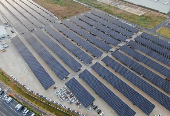
What Makes Fleet-Depot Solar Carport Layout Different?
A fleet depot is an active logistics area, not a static parking lot. Vehicles may have different lengths and turning radii, dwell for different periods, and leave in waves. Charging demand may be concentrated before dispatch rather than spread evenly through the day. Those conditions change the value of bay width, column spacing, charger reach, and canopy orientation.
The layout should therefore connect three plans from the beginning: the vehicle circulation plan, the charging plan, and the structural plan. A canopy that maximizes module area but blocks a turning path is not an efficient design. A charger positioned close to a transformer may still be wrong if its cable crosses a pedestrian route or a vehicle door.
Our solar carport structures provide a useful structural reference, but the final layout must be developed from the fleet’s operating data and the site’s physical limits.
How Do Fleet Operations Shape Solar Carport Geometry?
Which Vehicle and Dispatch Inputs Set the Geometry?
Begin with the vehicle envelope rather than a standard parking-bay assumption. Record vehicle length, width, height, door swing, charging-port location, reversing movements, and the clearances needed for emergency and service access. Articulated vehicles and delivery vans can need very different paths even when they occupy similar nominal areas.
Next, map the operating rhythm. A workplace fleet that remains parked for eight hours can use lower-power daytime charging that aligns with PV output. A delivery fleet that returns in a short evening window may need higher simultaneous charging and more deliberate queue space. The canopy should protect the charging positions that matter operationally, not simply cover the easiest rectangle.
How Should Row Arrangement Balance Flow and Structure?
Row arrangement also matters. Double-row canopies may use steel efficiently, while single rows can simplify traffic flow on constrained sites. Cantilevered edges can reduce columns near doors or mirrors, but they may increase beam depth and foundation demand.
As an illustrative scenario, shifting a column by 0.5 m can preserve a turning path or keep a charger cable away from a door opening. The change may reduce one parking-bay dimension while improving the depot’s usable throughput. That trade-off should be tested in the vehicle path model before structural drawings are frozen.
Where Should EV Fleet Charging Canopy Columns Be Positioned?
How Should Columns and Protection Follow Vehicle Movement?
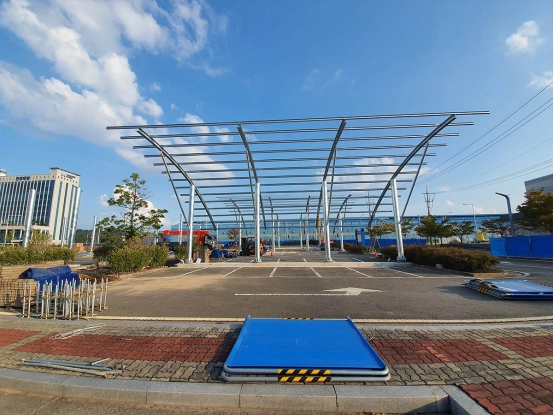
Column placement should follow the interaction between vehicle clearance, charger reach, impact protection, and foundation feasibility. Keep columns outside the swept path wherever possible, and coordinate bollards with the actual front and rear overhangs of the fleet. A nominally clear aisle can become unusable when a vehicle turns with a cable connected.
How Should Charger and Cable Routes Be Coordinated?
Charger position also affects the canopy’s serviceability. Cable paths should not cross doors, accessible routes, or vehicle lanes without a deliberate protection detail. Coordinate switchgear, emergency isolation, and communications routes with the steel frame before fabrication. The objective is a clean interface between a solar ground mounting system approach and the depot’s electrical layout, even though the canopy uses a different foundation arrangement.
How Should Solar Generation Match Fleet Charging?
Rated charger power alone is not enough to size the PV field. Compare the fleet’s charging load by hour with expected solar production, building demand, grid import limits, and any export constraints. A depot with vehicles parked during midday may use a larger share of its PV directly. A fleet that charges after sunset may need managed charging, storage, or a different economic case.
The design should define the control objective before selecting equipment. Possible objectives include reducing a demand peak, increasing solar self-consumption, supporting a limited transformer, or prioritizing charging before a dispatch deadline. Each objective changes the required power and energy profile.
Managed charging can distribute available power across vehicles without exceeding a site limit. Inverters, chargers, battery controls, and building loads must exchange the data needed for that decision. A storage system should be evaluated against a defined operating need rather than a fixed battery-to-PV ratio. Where orientation or tracking is under consideration, the solar tracking system discussion should be tied to the canopy’s geometry, shading, and moving-equipment constraints.
What Commercial Solar Carport Design Constraints Affect the Layout?
Which Structural and Material Constraints Shape the Canopy?
The preferred operating layout must still satisfy local structural and electrical criteria. Wind uplift, snow, seismic effects, soil conditions, foundation reactions, and connection design determine whether a proposed span and column grid are practical. Material and coating decisions should reflect the site’s exposure, including coastal air, industrial pollutants, or road salt.
How Do Drainage and Electrical Access Change the Plan?
Drainage is part of the layout. Gutters and downpipes should keep water away from chargers, foundations, pedestrian paths, and vehicle doors. Cable trenches, grounding conductors, surge protection, emergency isolation, and equipment access should be coordinated with the same plan. Battery enclosures or switchgear may introduce separation and access requirements that force a canopy edge to move.
How Should the Module-to-Rail Interface Be Approved?
The module-to-rail interface also belongs in the design review. A clamp must seat on the frame and rail as an approved assembly; abrazaderas de panel solar cannot be selected independently of module geometry, rail profile, and fastener documentation.
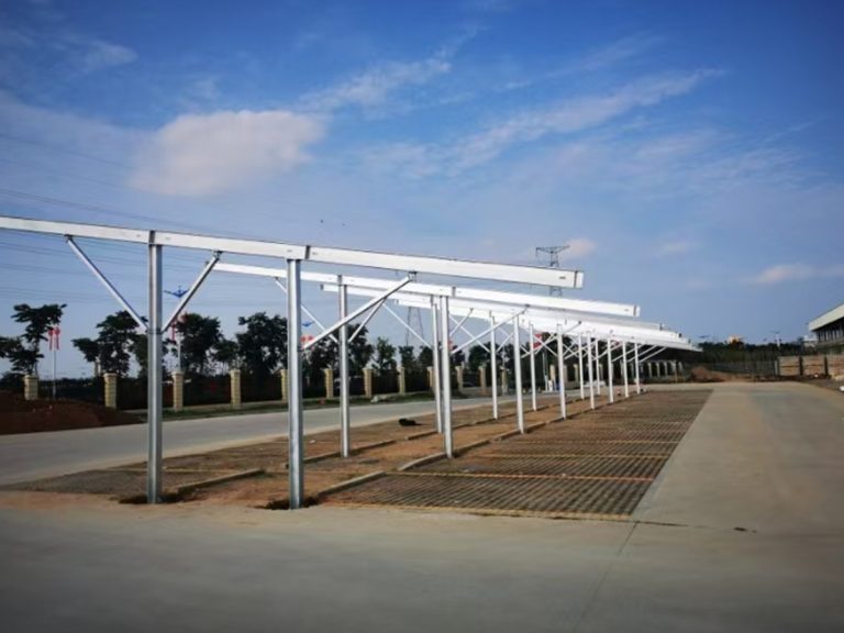
How Can Teams Validate a Fleet-Depot Layout Before Release?
Before detailed design or fabrication, the project team should be able to trace the layout back to an approved site plan, vehicle path study, charger schedule, structural basis, equipment-clearance drawing, drainage route, and local design loads. These documents should share the same revision and reference grid.
The release decision is stronger when one coordinated drawing set shows columns, chargers, bollards, cable routes, foundations, module rows, access lanes, and emergency equipment together. A review that checks only module count or steel quantity can miss the operational conflict that matters most to the fleet.
Preguntas frecuentes
Can an Overnight Fleet Still Benefit from a Solar Carport?
Yes. The value depends on daytime site loads, export conditions, managed charging, and whether storage can shift solar energy into the fleet’s charging window. The canopy can also provide parking coverage even when direct PV-to-vehicle use is limited.
Should Every Fleet Depot Use a Column-Free Canopy?
No. Column-free spans can improve vehicle movement, but they may require deeper beams, larger foundations, and more steel. Use them where the operational gain justifies those structural consequences.
Does Battery Storage Set the Solar Carport Size?
No. PV, chargers, site load, grid capacity, and storage should be sized around a defined operating objective. A fixed battery-to-array ratio does not capture the fleet’s schedule or demand peaks.
What If Existing Parking Lines Conflict with the Best PV Orientation?
Preserve safe vehicle movement first, then compare alternate bay orientations, canopy spans, and electrical routes against the site’s energy and structural priorities. A slightly less optimal azimuth may produce a better depot when it avoids circulation conflicts.
Discuss Your Fleet-Depot Solar Carport Layout
To begin a coordinated review, send your depot layout data with the site plan, vehicle dimensions, dispatch schedule, charger data, module preference, local wind or snow criteria, and foundation assumptions. That information lets the structural and energy decisions develop around the way the depot actually operates.






 Spanish
  English
  Japanese
  Korean
  Arabic
  Russian
  French
  Thai
Thai