

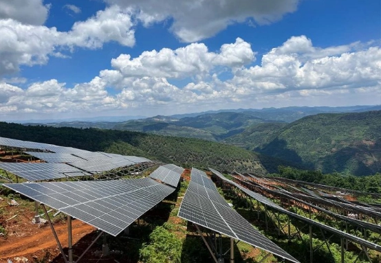
Wind damage often begins quietly. A connection loosens. A post leans. Repeated uplift works on a rail. A useful calculation starts with the site and follows the force through the structure. This guide covers a preliminary method for ground-mounted PV arrays. Final values still need project-specific structural review.
What Is Wind Load on a Ground-Mounted Solar Structure?
Wind load is the pressure or suction acting on the module surface and the steel beneath it. On an open-rack array, wind can pass under and between the modules. The behavior differs from a solid roof or closed wall.
Three effects usually control the design. Positive pressure pushes against the modules. Negative pressure creates uplift. Horizontal force and its lever arm produce an overturning moment at the posts and foundations.
Wind pressure is force per unit area, measured in Pa or psf. Wind force is pressure multiplied by effective area. Selecting the coefficient and tracing the load to the soil takes more care.
Input Data Required Before Starting the Calculation
Site data sets the quality of the result. Gather the following information before opening a spreadsheet.
Design Wind Speed
Use the design wind speed required by the local code or project specification. Confirm whether it is an ultimate or allowable-stress value. Check the unit. A value in km/h cannot enter an equation that expects m/s.
The risk category matters. A public facility and a critical utility installation may not use the same return period. A weather app reading is not a design value.
Site Exposure and Topography
Describe the terrain around the array. Open farmland develops a different wind profile from a coastal edge or suburban site. Hills and ridges can accelerate the flow. Nearby buildings may provide shielding, but that benefit needs a code-based assessment.
Module height above grade matters because wind speed generally increases with height.
Solar Array Geometry
Record the module dimensions and tilt angle. Add clearance above grade and row spacing. Note the table configuration. Orientation affects the critical wind direction.
Edge and corner modules deserve special attention. A gust can wrap around the perimeter and create higher local suction than at the center.
Structural and Foundation Information
List the rail sections and posts. Document the clamps, bolts and foundation type. Include material grade and corrosion protection. Checking a rail while ignoring bolt pull-out leaves the load path incomplete.
Step-by-Step Method for Calculating Wind Loads
This method is a preliminary framework. Final coefficients and load combinations should come from the applicable standard, such as ASCE 7 or EN 1991-1-4.

Step 1 — Determine the Design Wind Speed
Start with the code wind map or local authority. Apply the required risk and exposure factors. Account for topography and wind direction. Standards may use different gust periods. Convert only as the code permits.
Step 2 — Calculate the Basic Wind Pressure
For a simple SI-unit estimate, use:
q = 0.613 × V²
Here, q is basic wind pressure in pascals and V is wind speed in metres per second. This is an early-design check, not a replacement for the code velocity-pressure procedure.
Step 3 — Apply Pressure and Force Coefficients
Convert basic pressure into design pressure with the coefficient required for the array geometry:
p = q × C
The coefficient ซี may incorporate exposure and gust response. It can also cover directionality and net pressure. Tilt angle, row spacing and array height can change the result. No universal coefficient suits every PV installation.
Use the correct sign. Positive pressure pushes toward the array. A negative net pressure can pull the modules away from the support rails and create uplift at the connections.
Step 4 — Convert Pressure into Wind Force
Apply design pressure to effective area:
F = p × A
F is wind force in newtons. A is projected or effective area in square metres. The area depends on wind direction and the selected code. Do not use full plan area automatically when only part is exposed in the critical load case.
Step 5 — Check Uplift, Sliding and Overturning
Calculate uplift at module and rail connections. Determine horizontal shear at each post. Overturning moment depends on force and height above the foundation.
Compare these actions with foundation resistance. Driven piles require geotechnical capacity. Ground screws require pull-out and lateral data. Concrete footings need checks for overturning, sliding and soil bearing.
Step 6 — Distribute Loads Through the Structure
Follow the force from the module frame through each connection to the foundation. Check rail bending and deflection. Review post bending plus bolt shear and tension. Check weld strength where welding is used. The lowest-capacity component may control the design.
Illustrative Wind-Load Example
Consider a hypothetical array with a design wind speed of 40 m/s. The preliminary basic pressure is:
q = 0.613 × 40² = approximately 981 Pa
Assume an illustrative net pressure coefficient of 1.3. The estimated design pressure becomes:
p = 981 × 1.3 = approximately 1,275 Pa
For an effective exposed area of 2.0 m²:
F = 1,275 × 2.0 = approximately 2,550 N
This example shows the calculation path only. Coefficient, edge-zone treatment and load combinations must be selected for the actual project. Foundation design also requires soil information.
Common Mistakes When Calculating Solar-Structure Wind Loads
A common mistake is using a convenient wind value rather than the code value. Treating a large array as one uniform surface is another. Interior and perimeter modules can experience different suction.
Checking downward gravity load while skipping uplift can leave clamps, bolts or anchors under-designed. Building coefficients are also copied into PV calculations without considering open-rack geometry.
Row spacing and module height are easy to overlook. Tilt angle is another common omission. So are load combinations involving snow or seismic action. A rail check does not prove that posts and foundations are adequate. Record the assumptions and units. Keep the selected coefficients visible so another engineer can audit the calculation.
How CZT Solar Can Support Your Ground-Mounted PV Project
Wind loads are easier to manage when components are coordinated early. CZT Solar provides customizable PV mounting systems with steel sections and connection parts suited to project geometry.
For tailored framing, steel channels for solar structures can be evaluated alongside custom metal components. Connection requirements can be matched with solar installation hardware. For a quotation, provide the site location and design wind speed. Add the array dimensions plus tilt angle. Foundation type and estimated quantity are also needed.
Planning a ground-mounted solar project? Contact CZT Solar and share the site wind data and array requirements to discuss a suitable mounting-system configuration.
FAQ: Wind Loads for Ground-Mounted Solar Structures
Q: What wind speed should be used for a solar mounting system?
Use the design wind speed required by the local code and project risk category. A forecast or a general regional average is not a substitute.
Q: Do ground-mounted solar panels need uplift calculations?
Yes. Negative pressure can lift modules and rails. Uplift resistance must be checked with sliding and overturning.
Q: Is the basic wind-pressure formula enough for final design?
No. It supports preliminary estimation. Final design requires project-specific coefficients and load combinations. Component checks and foundation verification are also required.






 Thai
Thai  English
  Japanese
  Korean
  Spanish
  Arabic
  Russian
  French