

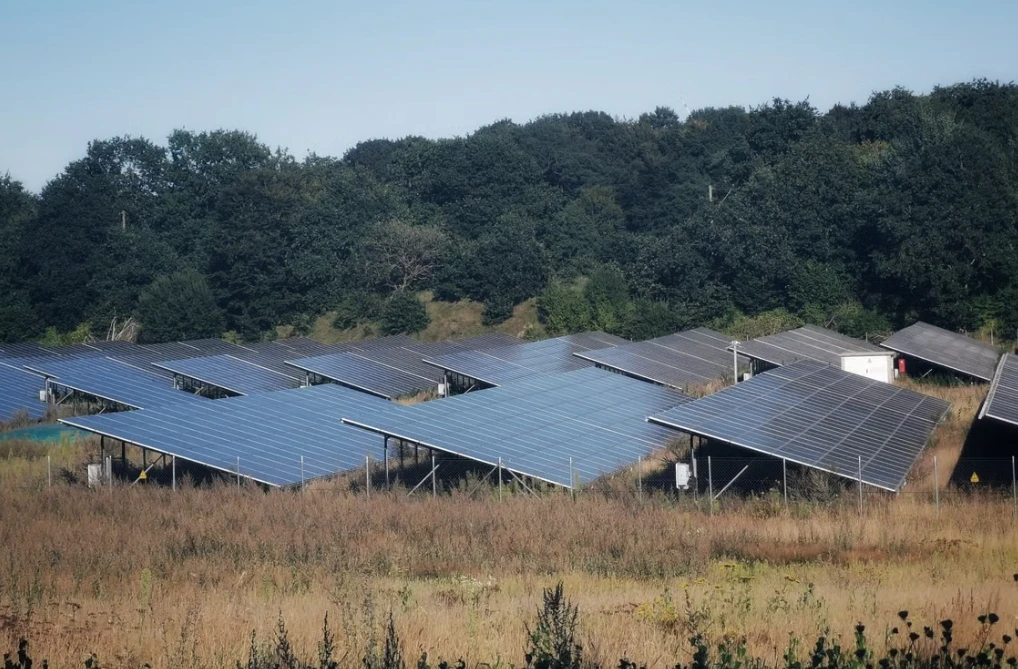
Wind damage usually starts at an exposed corner, a loose clamp, or a foundation with insufficient uplift capacity. Once one connection moves, the load path changes.
A useful solar mounting structure wind load calculation must match the site. Wind climate, terrain, array height, panel tilt, support spacing, and foundation type matter. A catalog wind rating is not a project design. Final calculations should be checked by a qualified structural engineer under the governing code.
What Is Wind Load on a Solar Mounting Structure?
Wind load is the pressure and suction created as air passes over, beneath, and around a PV array. The structure may experience uplift, downward pressure, and horizontal drag together.
The load is not uniform. Corner and perimeter modules often attract higher pressures than interior modules. Rooftop arrays also interact with roof edges and parapets. A low fixed-tilt table in farmland does not behave like the same layout on a warehouse roof.
What Information Is Needed Before the Calculation?
Missing dimensions often lead to conservative assumptions.
1. Basic Design Wind Speed
Use the code-defined wind speed for the project coordinates and risk category. Do not use an average weather-station value or a gust from an app.
2. Terrain and Exposure Category
Open coast, desert, farmland, suburbs, and dense urban areas create different wind profiles. Hills and sudden terrain changes may increase pressure.
3. Structure Height
Record roof height, module elevation, ground clearance, and post height. Greater height generally increases velocity pressure and foundation moment.
4. Panel Dimensions, Tilt and Orientation
Provide module length, width, tilt, orientation, row spacing, gaps, and table dimensions. A 10-degree rooftop array should not use coefficients from a 30-degree ground mount.
5. Mounting and Foundation Type
Define the support system: roof anchors, ballast, standing-seam clamps, driven piles, ground screws, concrete foundations, or tracker posts. Connection spacing and tributary areas are essential.
How to Calculate Wind Loads for a Solar Mounting Structure
The calculation converts site wind speed into pressure, then pressure into forces and reactions. Code notation changes. The load path does not.
Step 1: Select the Applicable Wind Design Standard
Use the standard required by the jurisdiction. Common references include ASCE 7 in the United States, EN 1991-1-4 with the relevant National Annex in Europe, and AS/NZS 1170.2 in Australia and New Zealand. ASCE 7-22 contains provisions for rooftop and ground-mounted solar panel systems.
Do not combine wind speed from one code with coefficients or safety factors from another. They often are not compatible.

Step 2: Calculate the Design Velocity Pressure
In simplified form:
Velocity pressure, q = constant × exposure factors × design wind speed²
The factors may cover height, terrain roughness, topography, directionality, elevation, and risk. Check the exact equation and units.
Wind speed is squared. Raising the design speed from 40 m/s to 50 m/s increases the basic pressure term by about 56%, not 25%.
Step 3: Determine the Net Pressure Coefficient
Select coefficients for the actual geometry and wind direction. Check panel tilt, clearance, roof zone, row position, and mounting type. Interior, edge, and corner zones may require different values.
On a large rooftop project, a small group of corner modules may govern attachment spacing. Do not average that condition across the roof.
Step 4: Calculate the Design Wind Pressure
A general expression is:
Design wind pressure, p = q × Cnet
Here, Cnet is the applicable net pressure coefficient. Calculate positive and negative cases. Negative pressure represents uplift.
Keep gust factors, dynamic factors, and load combinations consistent. Trackers and flexible structures may require extra dynamic checks when movement or torsion matters.
Step 5: Convert Pressure into Structural Force
Convert pressure to force using the tributary area:
Wind force, F = p × A
Then follow the reaction:
Module → clamp → rail or purlin → beam → post or roof attachment → foundation or building frame
A rail can pass while a clamp slips. A post can pass while a pile pulls out. The weakest part controls.
Simple Wind Load Calculation Example
Assume a design wind pressure of 1.2 kN/m² acts over an effective area of 2.4 m²:
F = 1.2 × 2.4 = 2.88 kN
The force is 2.88 kN for that area. It is not yet the final reaction. Pressure direction, zone coefficients, safety factors, load combinations, and support distribution still apply.
Dividing the force equally between four clamps may be convenient, but equal sharing is not always valid. Rail flexibility, clamp position, frame stiffness, and eccentricity can shift the reactions.
Structural Components That Must Be Checked
The main checks normally include:
- module frames, approved clamp zones, clamp slip, and bolt capacity;
- rail or purlin bending, shear, torsion, and deflection;
- beam and post strength, buckling, bolts, welds, and splice plates;
- roof fastener pull-out and supporting roof-member capacity;
- pile uplift, lateral resistance, and ground-line bending;
- ballast sliding, uplift, and overturning;
- corrosion protection at welds and cut edges.
On coastal sites, a connection may pass the strength check and still become a maintenance problem if coating damage is ignored.
Common Wind Load Calculation Mistakes
Using the wrong wind speed is common. Applying one pressure value to the entire array is nearly as common.
Other errors include ignoring corner zones, treating roof and ground systems as equivalent, checking only the primary steel, and trusting a generic wind rating without confirming its geometry. Local post uplift is also easy to miss.
Ballasted roofs need a sliding check, not just an uplift-to-dead-weight comparison. Trackers need a stow-angle assumption that matches the control strategy and possible power loss.
How CZT Solar Supports Wind-Resistant Mounting Projects
CZT Solar supplies fixed PV brackets, tracking brackets, photovoltaic carports, flexible brackets, BIPV systems, ground and roof mounting systems, accessories, and customized metal components.
For high-wind projects, the discussion should begin with location, standard, module layout, tilt, wind speed, snow load, soil information, roof structure, corrosion category, and installation constraints. Member sections, bracing, connections, piles, and protective finishes can then be adjusted around the design reactions.
A mounting supplier should not replace the local engineer. Good manufacturing support turns the calculation into buildable parts, controlled tolerances, and connections installers can assemble without improvisation.
Frequently Asked Questions
Q: How much wind can a solar mounting structure withstand?
There is no universal value. Capacity depends on wind-speed definition, exposure, geometry, materials, connections, foundations, and load combinations. Any quoted wind resistance should include its assumptions.
Q: Does panel tilt affect wind load?
Yes. Tilt changes airflow above and below the module, affecting uplift, downward pressure, and drag. A modest change can alter the governing coefficient.
Q: Which part of a solar mounting system usually fails first?
Often the least forgiving connection: a clamp, bolt, roof anchor, splice, or foundation interface. Small components receive less attention, but carry the same load path.
Q: Do ground-mounted solar panels need wind load calculations?
Yes. Ground mounts require checks for uplift, lateral load, member bending, connection capacity, pile pull-out, ground-line moment, and overturning. Open terrain can make wind govern even for a low structure.
Conclusion
A sound solar mounting structure wind load calculation uses the correct site wind speed, exposure, height, geometry, pressure coefficients, and tributary areas. The engineering work continues through every clamp, rail, post, anchor, and foundation.
For a project-specific mounting proposal, send CZT Solar the site location, module arrangement, tilt angle, governing code, environmental loads, and available soil or roof data. Those details are more useful than a generic request for a “high-wind bracket.”







 Russian
  English
  Japanese
  Korean
  Spanish
  Arabic
  French
  Thai
Thai